SolidificationPatent
Baffles fixed to the shell even out the temperature field during single-crystal withdrawal
An SJTU application: ceramic-fibre plates at critical levels of the mould block vertical radiation and reduce front tilt. Lower freckle and stray-grain tendency is claimed.
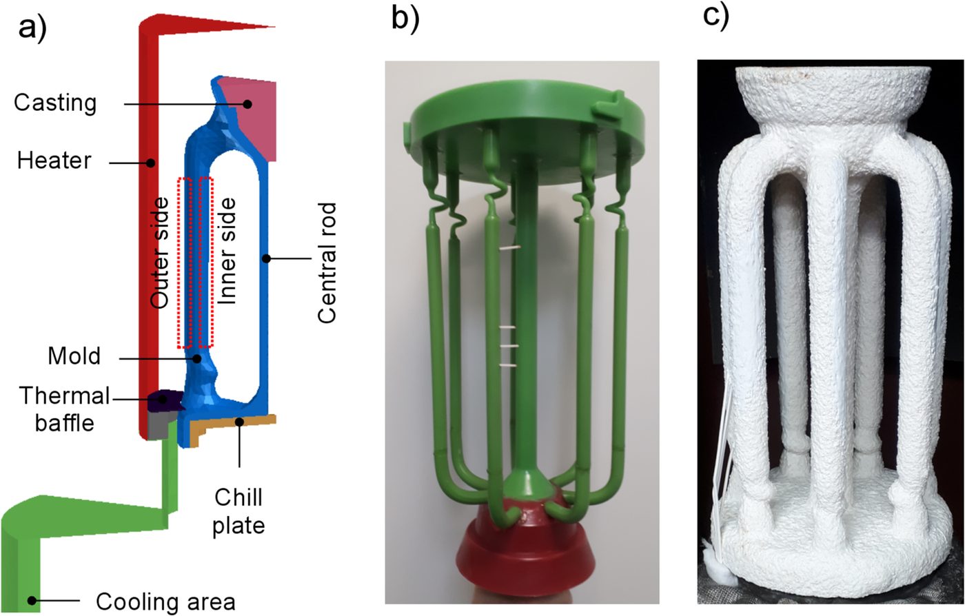
Single-crystal blades for aero-engines and heavy-duty gas turbines are almost always cast by Bridgman directional solidification. There are two variants: high-rate solidification with radiation cooling (HRS) and liquid-metal cooling (LMC). HRS is more widespread – the equipment is simpler and easier to run. But in HRS radiation decides everything: the mould and the melt in it are hot, and as they are lowered they lose heat by radiation to the cold walls of the lower chamber. The distribution of that radiation sets the temperature field in the metal.
Shanghai Jiao Tong University proposes to control that radiation on the mould itself – with baffles fixed to the shell.
Where the front tilt comes from
While the water-cooled chill has not yet been lowered, the gap between the hot and cold zones is the narrow slot between the chill and the furnace baffle. Once it moves down, the gap between the baffle and each blade in the cluster widens sharply. Radiation from the hot zone passes down into the cold zone, and the mould surface heats unevenly – the centre and the edges of the cluster cool differently. The solidification front tilts, the width and shape of the mushy zone start to wander, and growth directionality suffers.
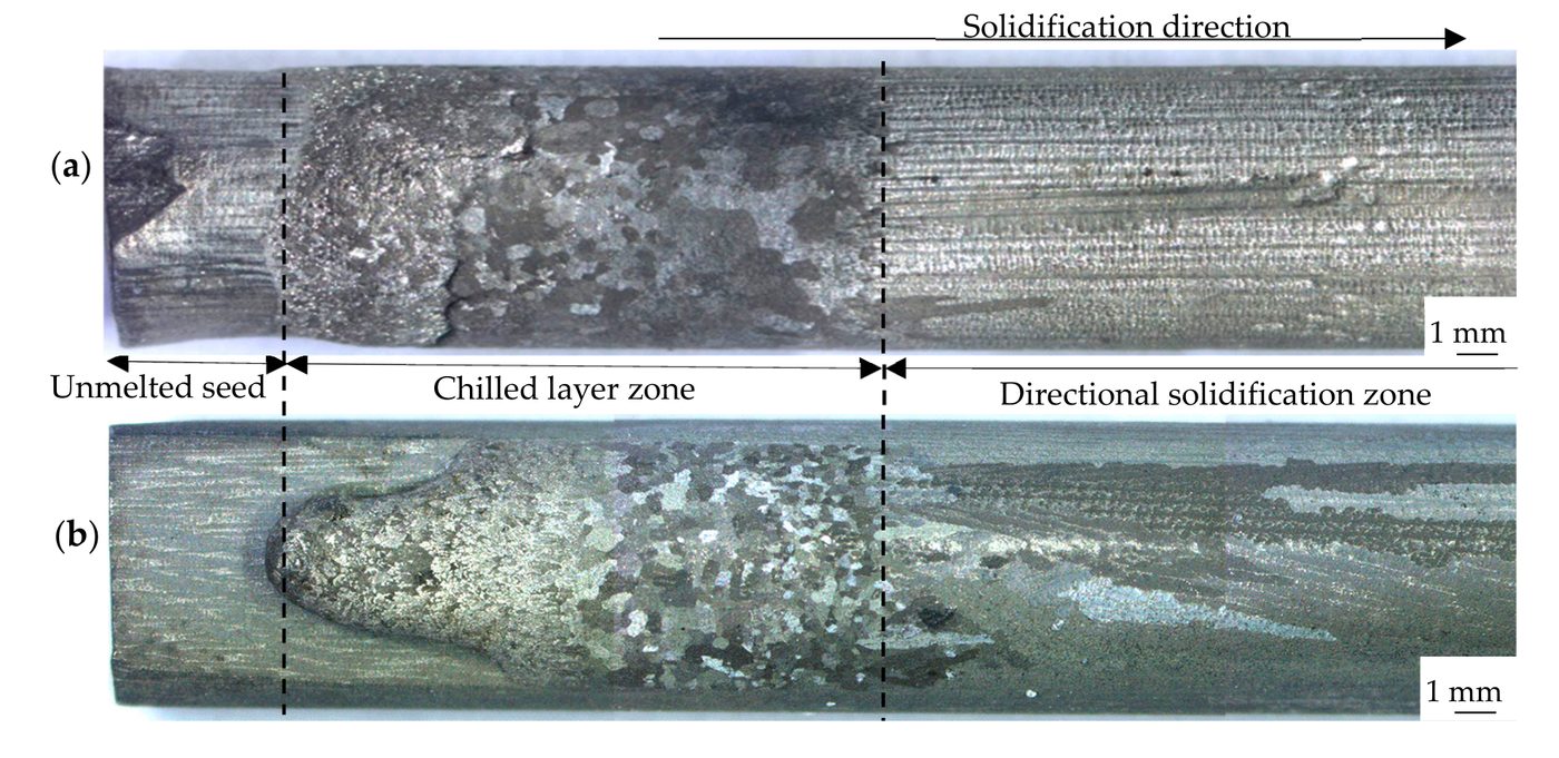
According to the application, freckles appear mainly in thin tapering parts of the airfoil, and stray grains where the mould sticks out sharply sideways. The worst moments are when the wide mould base passes below the furnace baffle and when the cluster cross-section increases abruptly.
What has been tried before
The application lists its predecessors candidly, and the list is useful in itself:
- a group at RWTH Aachen placed heat-conducting blocks where the mould cools too fast, redistributing heat – which suppressed stray grains on long platforms;
- a group at Northwestern Polytechnical University made a shell of uneven thickness, thickened at the root, to delay premature radiation and reduce stray grains there;
- a group at the Institute of Metal Research of the Chinese Academy of Sciences placed a heating block in the centre of the cluster to make up for vertical heat loss from the centre and the shadow effect in large-diameter furnaces – against freckles;
- a group at Tsinghua University varied the withdrawal rate in real time to match the movement of the front.
The drawback of all of these, in the applicant's view, is that they are tied to a specific blade, need long development or a large body of trial data, and transfer poorly to blades of other shapes. The application claims a more general approach.
What is claimed
The main claim: one or more auxiliary baffles are fixed to the shell at set locations, with a ratio of baffle thermal diffusivity to shell thermal diffusivity between 0.6 and 1.5. The point of the condition is that the baffle and the adjoining shell heat up and cool down in step and create no extra temperature difference. At the same time the baffle's conductivity is low, so a marked temperature difference forms above and below it – the baffle cuts off radiation from the mould in the hot zone to the cold chamber and to the already cooled part of the mould.
The dependent claims add detail:
- the baffle has openings matching the contours of the shells and the central post at that level;
- its projection on the horizontal plane fully covers the chill;
- its conductivity is no more than 1 W/(m·K);
- it is no thicker than the shell and thinner by 1–2 mm;
- the horizontal clearance between baffle and furnace baffle is no more than 10 mm;
- withdrawal is stepwise with variable speed tied to the baffle positions.
The example in the application
What the example looks like
The furnace has a cylindrical chamber: the baffle between the hot and cold zones is a disc with a 130 mm opening, the chill is 120 mm. The auxiliary baffle is a ceramic-fibre board disc 120 mm in diameter and 5 mm thick, like the shell; when lowered to the furnace baffle a 5 mm clearance remains. On a three-blade cluster the disc is cut into three pieces along the contours of the shells and the central post, bonded with silica sol and fixed by firing with a material whose thermal properties match the shell. The alternative is to set thin mica sheets into the shell when about half the coats are on and continue dipping.
There are placement rules too. Baffles are spaced no closer than 30 mm vertically; for small blades with an airfoil of about 100 mm, no more than three. The baffle edge should project at least 20 mm beyond the shell, so that it still blocks radiation once the mould is 30 mm or more from the furnace baffle, and the clearance to the furnace baffle should be at least 3 mm so that the disc does not catch it on the way down.
The first baffle goes at the junction of the grain selector and the casting: below it, on the selector, the withdrawal rate stays as before so as not to risk grain selection. The last one goes where the mould cross-section steps up. Between the first and last baffle the rate may be raised by up to 2.5 mm/min, and above the last by up to 1.5 mm/min, over the original process window. The baffles insulate the mould above them better and cool it below them better, which, as the authors intend, allows faster withdrawal.
What supports it
The description evaluates the effect by numerical simulation, using the height difference between the highest and lowest points of the liquidus isotherm across the section. In the model the field tilt starts to grow sharply as the front enters the airfoil – about 80 mm from the bottom of the casting – and peaks on entering the root. A baffle at the start of the airfoil clearly reduces the tilt over the airfoil, and a baffle where the cross-section steps up, at about 130 mm, lowers the stray-grain risk. The application contains no data on real castings or scrap rates and names no alloy.
The applicants are the same SJTU group (Li Jun, Li Jianguo, Xia Mingxu, Ren Neng) that publishes on defects in single-crystal blades.
Source
- Number
- CN121715541A (application CN202512060121.6)
- Applicant
- Shanghai Jiao Tong University
- Inventors
- Ren Neng, Li Jun, Zeng Long, Xia Mingxu, Li Jianguo
- Filed
- 31 December 2025
- Published
- 24 March 2026
- Status
- Application, not granted
- Title (Google Patents translation)
- Preparation method of high-temperature alloy single crystal blade for mold shell auxiliary radiation heat transfer control
- Evidence
- Claimed in a patent
- Read from
- the description and claims
Open the source: Google Patents ↗ Espacenet ↗
Added: 3 November 2026.